Difference between revisions of "Low Level"
Jump to navigation
Jump to search
Image:
Elcanoadmin (talk | contribs) (→Functionality:) |
Elcanoadmin (talk | contribs) |
||
| Line 10: | Line 10: | ||
* Runs on 3.3V of power internally with power provided to the Arduino DUE through a 5v regulator on the DBW board | * Runs on 3.3V of power internally with power provided to the Arduino DUE through a 5v regulator on the DBW board | ||
* Steering and throttle headers added to lower connector size | * Steering and throttle headers added to lower connector size | ||
| + | [[File:SteeringJ8.PNG|200px|Steering Connector J8]] [[File:MotorJ7.PNG|200px|Motor Connector J7]] | ||
* RJ-45 adapter connected to steering pins | * RJ-45 adapter connected to steering pins | ||
* Brakes use solenoids instead of actuators | * Brakes use solenoids instead of actuators | ||
Revision as of 23:38, 5 August 2024
Contents
LowLevel v4 PCB
The V4 LowLevel PCB builds upon the V3.1 PCB. It still communicates over the CAN bus with the manual control or autonomous system from the receiver system. However, the new LLB is the daughter board for the Arduino Due microcontroller board.
Functionality:
- Uses binary control for steering as opposed to a PWM input
- LLB uses internal CAN bus module, removing the need for any external CAN modules
- Runs on 3.3V of power internally with power provided to the Arduino DUE through a 5v regulator on the DBW board
- Steering and throttle headers added to lower connector size


- RJ-45 adapter connected to steering pins
- Brakes use solenoids instead of actuators
- Creates file for outputting date and stores it in SD card
- PCF8523 RTC calculates and stores the following using system time:
- Milliseconds since compile time
- Epoch time
- Date (YYYY/MM/DD)
- Day of the week
- Standard time (HH:MM:SS) (AM/PM)
LowLevel v3.1 PCB
Functionality:
- The LowLevel Board (LLB) is a daughter board (shield) for an Arduino Mega microcontroller. It has been renamed "Drive-By-Wire". It implements drive-by-wire, turning a trike into a CAN-bus based vehicle compatible with commercial self-driving equipment. The LLB communicates over the CAN bus with the higher-level autonomous system or manual control from the receiver system. It directly manages the actuators: the throttle to the motor, the turning servo, and the brakes.
- Motion directives are received on a CAN bus interface, processed, and articulated.
- System status (turn angle, wheel linear velocity) is reported back to CAN bus.
- LLB v3.x has the following interfaces:
- One CANbus channel on two connectors; a DB9-M and a three-pin screw terminal. The board includes a 120 ohm terminating resistor.
- X3 Motor (DB-15M): Interface to E-bike controller
- Analog voltage (approximately 0v to 4v) output to hub motor throttle
- Digital outputs for activating reverse and regenerative braking.
- PWM output for PWM-operated braking (no longer used)
- Analog inputs for hall sensor feedback from motor controllers supporting this feature. These inputs are NOT 5V SAFE. They absolutely require external supporting circuitry.
- A few spare connections for future expandability, such as a second DAC output and one digital GPIO.
DETAILS > DB15M
- Steering Header (RJ45):
- Two sets of pins to support analog potentiometers (5v, signal input, ground) giving angle of front wheels
- One PWM output (with its own ground) to drive the steering actuator.
- This cable is broken out into its component signals using an RJ45 patch jack, mounted near the steering actuator.
- X4 (ODO): Cyclometer (reed switch) input jack. This is pulled high by default, and brought low when the magnet passes the sensor.
- High current pluggable terminal for solenoid brakes:
- Connections for ground, 12v, and 24v.
- Two relay outputs to solenoids: on/off and 12/24V.
- Steering Header (RJ45):
- The LowLevel runs on 5V power, and provides outputs for sensors. Note that the Arduino Mega 2560's regulator has a fairly low current limit, and should not be used for any significant current supply. The Arduino's DC input jack accepts 12V, and its USB port may be connected to a typical USB power supply. The 12V is provided by a DC-DC converter from the main battery (36 to 50V).
Image: 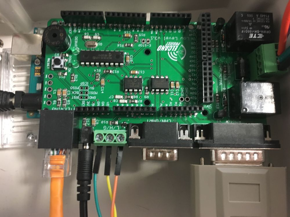

NEXT > High Level
LowLevel v2.1 PCB
Functionality:
- Version 2.1 used UART serial connections to other boards instead of the CAN bus. It interprets messages from higher-level autonomous systems or manual controls (RC, joystick). It directly manages the state of the actuators; the hub motor, the turning servo, and the brakes.
- Depending on the current firmware or operating mode, motion directives are received on one of three interfaces;
- ElcanoSerial from the combined C3/ C4/ C6 High Level board
- RC receiver
- Manual Joystick
- LLB v2.x has the following low-level interfaces:
- X2 Cruise (DB-25F) - ElcanoSerial messages from High Level.
- X3 Motor ( DB-15M): Analog voltage (0,4v) output hub motor.
- X1/X5 Turn Sensors (RJ45): SPI wheel angle sensor digital inputs. (Digital urn sensors were never implemented.)
- X4 (ODO): Cyclometer (reed switch) input jack. Board layout was incorrect. This signal needs to be jumpered to Arduino pin D2.
- JP9 (8 pin): Joystick analog input signals.
- JP12 (3 pin): Pulse output signal to steer.
- JP11 (3 pin): Pulse output signal to apply main brakes. (No longer used)
- JP5 (4 pin): Left wheel angle sensor analog input. (Little used since it covers 360 degrees and is less accurate)
- JP6 (4 pin): Right wheel angle sensor analog input. (Trike prefer this, since it is +/- 30 degrees, and more accurate)
- LLB v3.x makes significant wiring changes:
- Removes the ElcanoSerial connection and the DB-25F.
- Removes JP9, joystick analog inputs.
- Removes headers used to interface the RC receiver.
- Adds one CANbus interface on a DE-9F socket. For legacy compatibility UART serial is be available on this interface as well.
LowLevel v1.0 PCB
- The first version of the LLB was called MegaShieldDB. It had similar functionality, but different connectors. It had five DB connectors.
NEXT > High Level