SteeringSensor
Contents
Steering Angle Sensor
To change or maintain travel direction, the system must know which way the front wheels are pointing. Elcano tricycles accomplish this task with a rotational position sensor placed on the front steer wheels. Each trike has two steering columns, and both are instrumented for redundancy. The sensor is mechanically mounted to the shaft. Since the system uses Ackerman steering, the turn angle of the two wheels will be slightly different. More information is below. Rotational position sensors may be incremental or absolute. An incremental position sensor only reports discrete changes in rotational position and possibly direction of rotation. Absolute position sensors report the current angle of the sensor shaft. Absolute position sensors have advantages for sensing wheel angle, such as always knowing the current wheel angle at the power-on state. Elcano test vehicles use absolute rotation sensors.
Absolute wheel position: Analog
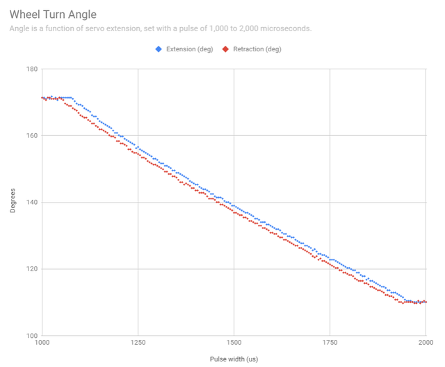
Analog position sensors typically communicate angle using current or voltage levels. In these devices, current or voltage is a function of the angle. Example:
Absolute wheel position: Digital
Digital position sensors communicate angle digitally. Two ways a sensor can accomplish this task is by encoding the measured position into a binary stream (serial communication) or by encoding the position in binary by driving several output pins high or low (parallel communication).
Reducing Sensor Noise
The problem with sending an analog signal over a long wire to the Arduino is that the wire acts as an antenna and picks up noise. Thus we connect a twisted wire pair from sensor to Arduino that has Signal In as well as the return. The return wire is connected to the ground wire at the sensor. The return wire may have picked up noise when it gets to the Arduino. The Arduino subtracts the analog value of return from the Signal In. Since both wires have picked up approximately the same noise, subtracting them gives a more robust reading. The Signal In return signal goes to an analog input on the Arduino, and is not connected to Arduino ground. The test vehicle analog sensor uses four wires: power, ground, signal, and signal return.
Another alternative is to use an analog-to-digital converter to digitize the voltage reading from the sensor before it reaches C2. All analog signals are sensitive to noise from the environment, especially nearby electronics. This noise appears as voltage changes on the power and signal wires of the turn sensors and is visible with an oscilloscope. Because noise creates changes in voltage on the signal and power wires, it creates erroneous angle readings.
--Main.JosephBreithaupt - 2017-02-11
Sensors used
We have gotten the best results from RTY060LVNAX 60 degree analog rotary encoder with a 5V range. Other possibilities:
- TT Electronics 6127 sensor giving 5V analog output over 360 degrees https://www.digikey.com/products/en?keywords=987-1393-ND . Has six times less resolution than a 60 degree sensor, and the minimum resolution can get lost in the noise.
- EMS22A50-M25-LD6 Digital rotary encoder. This produces 1024 steps over 360 degrees, in SPI. It will give a resolution of 0.35 degrees. Requires a change to Arduino.
- TLC1549CP 10-bit analog-to-digital converter with serial control. This could be used to digitize the voltage from the RTY060LVNAX, reducing noise from analog transmission. Requires a change to Arduino.
- AMS5043 Magnetic Angle Encoder. This requires that a cylindrical magnet be mounted precisely on the shaft. The sensor has an indent for the magnet, but the indent in not in the right place. Difficult to get robust readings from the part.
- It is possible to tap into the feedback wire on the linear actuator. This reading suffers from hysteresis.
- Putting a current sensor on the actuator lets us measure the power draw, but this is not adequate for control.
Mounting the Steering Angle Sensor
The steering sensor is mounted directly the top of the steering knuckle. In the top if the steering knuckle is threaded rod that is kept in place using a jam nut. On the end of that threaded rod is a coupling nut that has been locked in place using a jam nut. From the coupling nut an adapter has been 3d printed that connects the coupling nut to the Steering angle sensor. The steering angle sensor is help in place using a piece of flat metal bar with a 90 degree bend.
Mounting in this position is beneficial by reducing the amount of mechanical play that the system is exposed to and therefore reducing false readings.
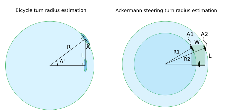
Ackermann Steering Geometry: wheel angle and turning radius
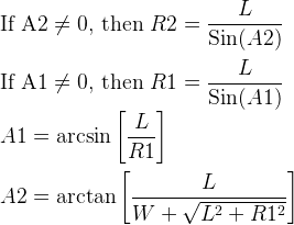
Many road vehicles use a variation of Ackermann Steering to allow a vehicle with more than two wheels to turn smoothly. The challenge of steering a multi-wheel vehicle in a circle is that all wheels are at different distances to the center of that circle, so they must turn to different angles and spin at different speeds. The trike used in the current Elcano system solves the speed differential problem by having only one drive wheel and un-driven steering wheels. The steering differential problem is solved using Ackermann steering geometry. With a basic understanding of Ackermann steering and right triangle geometry, we can predict variables like the turning radius of each wheel and the steering angle of the two front wheels. The inner turning wheel and outer turning wheel turn at different angles and have different turning radii. These calculations find both dimensions when given the inner turning radius (R1 in the image), wheelbase, and front wheel distance.
Ackermann steering geometry is based on two right triangles. Every calculation comes from right triangle trigonometry and the Pythagorean Theorem.
Variables:
Bicycle Image:
R = bicycle turning radius
A = bicycle front wheel angle
A' = A
L = wheelbase
Ackermann Image:
R1 = inner turning radius
R2 = outer turning radius
A1 = inner front wheel angle
A2 - outer front wheel angle
W = distance between front wheels
L = wheelbase
TODO: determine if these equations accurately predict the inputs from the turn angle sensors while the trike is stationary or moving.
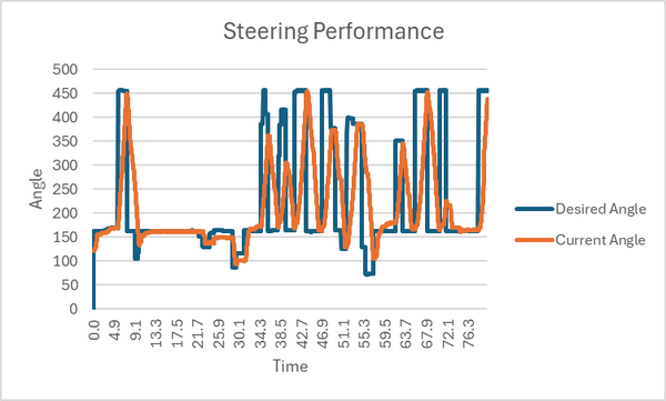
Steering state Summer 2024
Both prototype trikes are using the 60-degree angle sensors on the left wheel hub with the 360-degree angle sensor on the right wheel hub acting as a backup sensor. The current noise experienced from the left angle sensor is 10-15 analog read values or 48-73 mV recorded on the DBW v3 board and the resolution currently provided meets the current needs when steering with the RC controller. The steering angles are currently being returned through the steering board via an RJ-45 cable to the DBW board with each sensor having its own return line and power being provided locally from the steering board.


