CARLA Simulator
Contents
Current Functionality of Simulation
At the end our Autumn 2019 Capstone, we were able to deliver a demo that demonstrated communication between all components; high-level board (Arduino Due), low-level board (Arduino Mega 2560) with shield running low level code, router board (Arduino Due), and the instance of Carla. The instructions on how to reproduce the demo will be given later in this document. The primary roadblock that prevented further development into this project was the state of the CAN system of the Elcano trike (particularly the transceiver board which seems to have a flawed design). These are the current features of the simulator.
- Implementation of USB serial communication between router board and computer running simulator.py. Both entities (Computer and ArduinoDue) can send and receive data through USB connection.
- Implementation of a cyclometer. Router board can receive the current speed of the simulated vehicle in Carla and convert it into an interrupt-based cyclometer pulse, based on the wheel dimension of the Elcano. Also considers the random error of cyclometer present on the Elcano trike. This can be debugged with the built-in LED on the router board.
- Implementation of NMEA GPS sensor. Carla is able the output NMEA GPS data to the router board 10 times per second, effectively simulating the GPS sensor on the high-level board. Router board is successfully able to output it to UART serial which is how it is transmitted to the high-level board.
- Implementation of timing structure. Computer running simulator.py waits for data to be interpreted from the router board while the router board executes its update 10 times per second. This is the desired speed for both sensor data and actuation data to be updated.
- Implementation of vehicle control updaters through throttle, brake, and steering data. The computer running simulator.py can take desired throttle, brake, and steering and convert them into corresponding commands for Carla using Carla API. These commands move the vehicle within Carla. This is the primarily what the demo shows.
Demo Guide (How to Set-Up)
The following is a guide to set up the Elcano simulator.
Materials
- 1 Assembled Elcano Simulator Printed Circuit Board (PCB)
- 2 Arduino Due
- 1 Arduino Mega 2560
- 1 Box (200 x 150 x 70 mm)
- 2 Voltage Level Converter (included w/Simulator PCB)
- 1 SD Card (w/map files)
- 1 USB AB Cable (for Arduino Mega)
- 1 USB Micro Cable (for Arduino Due)
- 1 computer capable of running Carla
Pre-installation
Use the following instructions to install the required software to run the simulation.
- Python
- Install Python 3 (if not installed already)
- -experiments used version 3.7.6
- In a terminal, move to .\Simulation\
- Run the command “pip3 install -r requirements.txt” to have pip install all the required python libraries for the simulator
- CARLA
- Download CARLA (0.9.8)
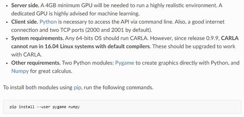
- CARLA requirements:
- Arduino Libraries
Download these Arduino libraries prior to running the simulation:- CAN_BUS_SHIELD by Seeed-Studio
- PID by Brett Beauregard
- Pin Change Interrupt by Nico Hood
- MCP48x2 DAC by Jonas Forsberg
- Arduino Due Timer Interrupts by Ivan Seidel
- Previous version of Arduino Due CAN Bus library is used but the necessary files are included within the repository.
- Elcano Repositories
The Elcano repositories are needed to run the simulation:

Run Simulation
Once all the requirements are installed, use the following instructions to run the simulation.

Step 1: Program all Arduinos
- Upload router_board_v1.ino to the router Arduino Due programming port
- Upload High_Level.ino to the high level Arduino Due programming port
- Upload Drive_By_Wire.ino to the low level Arduino Mega 2560
Step 2: Run CARLA
- Open a command prompt (type cmd in the windows search box)
- Go to the directory where CARLA is installed (CARLAUE4.exe)
cd C:\Users\bobross\Documents\ElcanoInstaller\CARLA\WindowsNoEditor- -You may have it saved to a different directory
- From the CARLA directory, type:
CARLAUE4.exe- Or, to run in low resolution mode:
CARLAUE4.exe -ResX=720 -ResY=480 -quality-level=Low
Step 3: Run Simulation
- Connect your PC to the native port on the Router Board Due
- Open a command prompt (type cmd in the windows search box)
- Go to the Simulation directory
cd C:\Users\bobross\Documents\Simulator\Simulation- -You may have it saved to a different directory
- From Simulation directory, start the Simulator UI
.\Simulation\start.bat
- By default, the Simulator UI will populate local running CARLA settings
- For control via the router board, leave mode as Auto
- To control via manual keyboard input, change mode to Manual.
- If running a network-based CARLA server, enter IP and Port of CARLA into the respective boxes. (i.e. 192.168.1.1, 2010)
- Click "Connect to CARLA"
- If Auto mode, it will pop up a selection of COM devices, select routerboard native port COM to begin and press go.
- If Manual mode, client will start with keyboard controls (WASD)
- Observe behavior in simulator.
- If car gets stuck, kill current simulator.py process and restart.
Debug/Logging
- High Level uses the Programming Port to display debug messages over serial monitor
- Router Board uses the Programming Port to display debug messages over serial monitor
Out of Scope Functionality Tested/Implemented
- Our project required us to delve into pieces of code within the Elcano project outside of our scope. Understanding of how sensors are read by the high and low-level boards is necessary for the simulation of the sensors. We were able to fix some issues regarding the CAN communication between the high and low-level boards. The modified low-level code was not pushed to the main low-level code folder in the repository on Github, however, it is included within the simulator documentation. The following were implemented.
- Unification of the proposed CAN message structure and the actual CAN message processing on the low-level code for CAN messages with ID 0x350 (High-level drive instructions). These are CAN messages the high-level will send to the low level to facilitate autonomy.
- Fixing the DAC output voltage by using the MCP48x2 library by Jonas Forsberg.
Bugs Within Simulator
- Occasionally the simulator and router board will desync and the NMEA GPS messages received by the router board will be faulty. This is usually followed by a crash of simulator.py. If not, simply press Ctrl^C and restart simulator.py.
- If simulator.py unexpectedly terminates, the created actors and sensors in Carla will not be properly destroyed. This usually does not cause problems for the simulation but proper termination in the future would be safer. For now if it is causing problems, simply restart Carla.
- Carla does not stop outputting sensor data even if asked to stop. This is a bug with Carla and not in our scope.
- Most malfunctions can be temporarily fixed by restarting the simulator.py instance.
- While we were able to implement the code for the low-level CAN interpretation of the throttle and brake commands from high-level CAN messages, coding for PWM requires additional testing.
Additional Notes
- Currently, the order that you output data from the router board to the computer running simulator.py is non-trivial. Data is interpreted based on the order which it is received.
- Carla sensor listening was flawed at the time this was made; .stop() would not stop the sensor from executing its attached function at each tick of Carla. Therefore speed was implemented without the use of sensors, and instead uses a command that accesses the speed only when needed. This is the suggested method until sensors are fixed. Certain sensors such as NMEA GPS, however, are only implementable using Carla sensors. Additional information can be found on Carla Documentation.
- In PowerShell, in CarlaUE4 path, run Carla as: ***Start-Process CarlaUE4 -ArgumentList “—quality-level=Low”*** to lower gpu load.
- Headless mode can be enabled for complete removal of graphics rendering, however, visual debugging is extremely useful.