Difference between revisions of "Low Level"
Jump to navigation
Jump to search
Image:
| Line 30: | Line 30: | ||
* The LowLevel runs on 5V power, and provides outputs for sensors. Note that the Arduino Mega 2560's regulator has a fairly low current limit, and should not be used for any significant current supply. The Arduino's DC input jack accepts 12V, and its USB port may be connected to a typical USB power supply. The 12V is provided by a DC-DC converter from the main battery (36 to 50V). | * The LowLevel runs on 5V power, and provides outputs for sensors. Note that the Arduino Mega 2560's regulator has a fairly low current limit, and should not be used for any significant current supply. The Arduino's DC input jack accepts 12V, and its USB port may be connected to a typical USB power supply. The 12V is provided by a DC-DC converter from the main battery (36 to 50V). | ||
| − | ==Image: [[File:LowLevel.JPG]] == | + | ==Image: [[File:LowLevel.JPG|1000px]] == |
Revision as of 05:30, 28 June 2019
Contents
LowLevel v3.1 PCB
Functionality:
- The LowLevel Board (LLB) is a daughter board (shield) for an Arduino Mega microcontroller. It implements drive-by-wire, turning a trike into a CAN-bus based vehicle compatible with commercial self-driving equipment. The LLB communicates over the CAN bus with the higher-level autonomous system or manual control from the receiver system. It directly manages the actuators: the throttle to the motor, the turning servo, and the brakes.
- Motion directives are received on a CAN bus interface, processed, and articulated.
- System status (turn angle, wheel linear velocity) is reported back to CAN bus.
- LLB v3.x has the following interfaces:
- One CANbus channel on two connectors; a DB9-M and a three-pin screw terminal. The board includes a 120 ohm terminating resistor.
- X3 Motor (DB-15M): Interface to E-bike controller
- Analog voltage (approximately 0v to 4v) output to hub motor throttle
- Digital outputs for activating reverse and regenerative braking.
- PWM output for PWM-operated braking (no longer used)
- Analog inputs for hall sensor feedback from motor controllers supporting this feature. These inputs are NOT 36V SAFE. They absolutely require external supporting circuitry.
- A few spare connections for future expandability, such as a second DAC output and one digital GPIO.
- Steering Header (RJ45):
- Two sets of pins to support analog potentiometers (5v, signal input, ground) giving angle of front wheels
- One PWM output (with its own ground) to drive the steering actuator.
- This cable is broken out into its component signals using an RJ45 patch jack, mounted near the steering actuator.
- X4 (ODO): Cyclometer (reed switch) input jack. This is pulled high by default, and brought low when the magnet passes the sensor.
- High current pluggable terminal for solenoid brakes:
- Connections for ground, 12v, and 24v.
- Two relay outputs to solenoids: on/off and 12/24V.
- The LowLevel runs on 5V power, and provides outputs for sensors. Note that the Arduino Mega 2560's regulator has a fairly low current limit, and should not be used for any significant current supply. The Arduino's DC input jack accepts 12V, and its USB port may be connected to a typical USB power supply. The 12V is provided by a DC-DC converter from the main battery (36 to 50V).
Image: 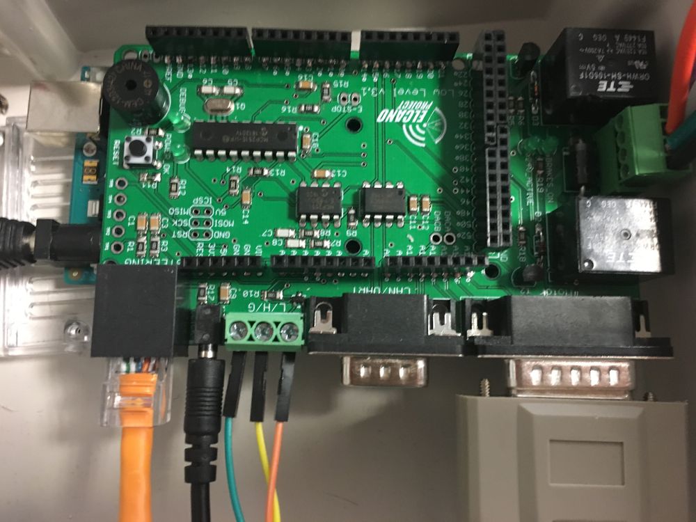

NEXT > High Level
LowLevel v2.1 PCB
Functionality:
- Version 2.1 used UART serial connections to other boards instead of the CAN bus. It interprets messages from higher-level autonomous systems or manual controls (RC, joystick). It directly manages the state of the actuators; the hub motor, the turning servo, and the brakes.
- Depending on the current firmware or operating mode, motion directives are received on one of three interfaces;
- ElcanoSerial from the combined C3/ C4/ C6 High Level board
- RC receiver
- Manual Joystick
- LLB v2.x has the following low-level interfaces:
- X2 Cruise (DB-25F) - ElcanoSerial messages from High Level.
- X3 Motor ( DB-15M): Analog voltage (0,4v) output hub motor.
- X1/X5 Turn Sensors (RJ45): SPI wheel angle sensor digital inputs. (Digital urn sensors were never implemented.)
- X4 (ODO): Cyclometer (reed switch) input jack. Board layout was incorrect. This signal needs to be jumpered to Arduino pin D2.
- JP9 (8 pin): Joystick analog input signals.
- JP12 (3 pin): Pulse output signal to steer.
- JP11 (3 pin): Pulse output signal to apply main brakes. (No longer used)
- JP5 (4 pin): Left wheel angle sensor analog input. (Little used since it covers 360 degrees and is less accurate)
- JP6 (4 pin): Right wheel angle sensor analog input. (Trike prefer this, since it is +/- 30 degrees, and more accurate)
- LLB v3.x makes significant wiring changes:
- Removes the ElcanoSerial connection and the DB-25F.
- Removes JP9, joystick analog inputs.
- Removes headers used to interface the RC receiver.
- Adds one CANbus interface on a DE-9F socket. For legacy compatibility UART serial is be available on this interface as well.
LowLevel v1.0 PCB
- The first version of the LLB was called MegaShieldDB. It had similar functionality, but different connectors. It had five DB connectors.
NEXT > High Level